


Silicon carbide (SiC) MOSFETs are increasingly being used in a wide range of industries, from electric vehicles and solar power to backup power systems. This is due to their ability to withstand high temperatures, provide faster switching, provide higher efficiency, particularly at higher voltages, and have a high current capacity.
Validating designs with SiC MOSFETs, on the other hand, presents some difficulties. The switching characteristics that make them appealing also present difficulties in obtaining accurate validation measurements. The appropriate probe selection and application can significantly improve measurement accuracy.
The Difficulties of Measuring SiC MOSFETs in Power Electronics Systems
The difficulties you will encounter when measuring SiC MOSFETs will be determined by where and how you measure. The gate voltage signal on the high side (VGS) is floating on a high, rapidly switching offset voltage, which is especially noticeable in high-side switches.
These “common mode” variations can cause ringing in the measurement system, making it difficult to determine whether the ringing is caused by the DUT or the measurement system.
The drain-to-source voltage (VDS) is much higher than the source-to-ground voltage (VGS) and is frequently floating with respect to earth ground. Drain current measurements must also be taken with caution to ensure adequate oscilloscope and probe bandwidth for accurate results.
Measurement of Silicon Carbide Gate Voltage with Accuracy
Measurements of gate-to-source voltage (VGS), particularly on high-side switches, can be difficult. When compared to VDS, which can be hundreds of volts, the gate threshold voltage is usually only a few volts.
Power management applications, such as chargers and adapters, are driving demand for silicon carbide (SiC) and gallium nitride (GaN) components in the brisk electric vehicle (EV) sector and consumer electronics devices.
Historically, these measurements have been made with differential probes such as the Tektronix THDP0200 Differential Probe. However, when measuring high-side VGS, using a differential probe may result in unnecessarily large design margins.
The voltage on the high-side MOSFET’s source terminal is rapidly changing in relation to ground. At high frequencies, an extremely high common mode rejection ratio (CMRR) is required to accurately perform this measurement.
Differential probe ringing can cause devices that are within specification to appear to be out of specification. Changing your design to slow down switching and eliminate spurious ringing will negate some of the advantages of using these high-speed SiC MOSFETs.
A high CMRR probe limits the effects of common mode voltage on the output. It is recommended that optically isolated probes, such as the IsoVu optically isolated probes, be used to enable more accurate measurements. At 1 GHz, these probes reject 80 dB of common mode signal, and at 100 MHz, they reject 120 dB. Figures 1 and 2 show an illustration of this effect.
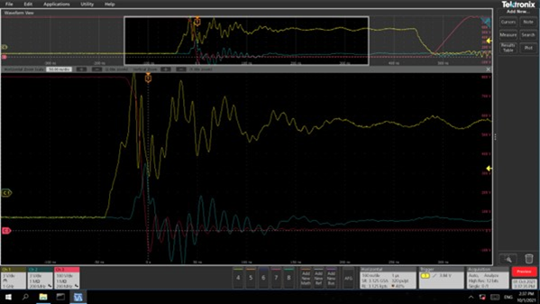
Figure 1: Gate voltage signals measured with a passive probe on the low side (yellow trace) and a differential probe on the high side (blue trace). This configuration exhibits significant ringing on the VGS signals, including the high-side drive signal.
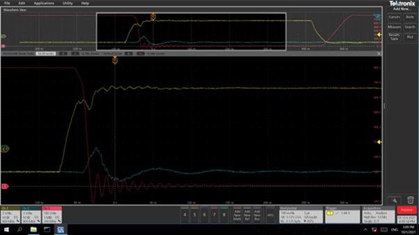
Figure 2: A gate voltage signal was observed using two optically isolated IsoVu probes (yellow & blue traces). The ringing has been greatly reduced, and the low-side gate signal can now be seen in detail (yellow). High common mode rejection removes spurious disturbances from the high-side gate signal (blue).
Measurement of Silicon Carbide Drain Voltage with Accuracy
Ground-referenced passive probes or differential probes can be used to measure drain voltage in SiC drivers. Ground-referenced probes are inexpensive and come with oscilloscopes, but they should only be used for ground-referenced measurements.
When a ground-referenced probe is connected to a floating (ungrounded) component, current flows through the ground lead. When using multiple ground-referenced probes, it is critical to ensure that all reference leads are connected to the same earth potential.
Never disconnect the ground pin from your oscilloscope’s power cord because this allows the scope’s chassis to float. This is a safety hazard and may have an adverse effect on measurement performance.